85+ Cellphone Charger Circuit Diagram Fresco. Just have to understand battery charging requirements only. This is the first automatic battery charger circuit. 15.04.2017 · working principle of wireless mobile charger circuit diagram.

Apresentado Cellphone Charger Using Bike Battery Soldering Mind
Use existing products to use more benefits. In this principle two lc tuned circuit communicate at same tuned frequency i.e. 14.02.2021 · the first circuit diagram below shows a precise temperature sensor circuit using the ic lm324.The diode d1 is a 1n4148 which effectively acts as the temperature sensor here.
The benefit of this indicator is that a. Ambient led light circuit diagram driver: Linear led driver circuit diagram 30v adjustable current: Three of its opamps have been employed here. Now some brands of smartphones …

Wireless mobile charger uses inductive coupling principle.. Not using ics and complicated devices. The lower npn transistor is bc547.

Triac dimmable led driver 14 w circuit diagram:.. Triac dimmable led driver 14 w circuit diagram: 14.02.2021 · the first circuit diagram below shows a precise temperature sensor circuit using the ic lm324. Led flasher circuit diagram with luxeon v star led: Linear led driver circuit diagram 30v adjustable current: Just have to understand battery charging requirements only. Use existing products to use more benefits. Here, we had use lc tuned to produce and transfer magnetic field which is received by another lc tuned circuit. You are able to ideally take advantage of this circuit for applications such as inverters, portable chargers, etc. The voltage across this diode drops by 2mv with every degree rise in temperature.

The lower npn transistor is bc547. This change in the voltage across d1 prompts a2 to change its output logic, which in turn. Tuned frequency of transmitter must be equal to tuned frequency of receiver.

We can use this circuit for all battery.. 15.04.2017 · working principle of wireless mobile charger circuit diagram. 1n4007 has a peak repetitive reverse voltage of 1000v with an. 13.05.2021 · the following design shows how to convert or upgrade the above circuit diagram into a regulated charger, so that the battery is supplied with a fixed and a stabilized output regardless of a rising voltage from the solar panel. Led flasher circuit diagram with luxeon v star led: You are able to ideally take advantage of this circuit for applications such as inverters, portable chargers, etc. Tuned frequency of transmitter must be equal to tuned frequency of receiver. 14.02.2021 · the first circuit diagram below shows a precise temperature sensor circuit using the ic lm324.. 13.05.2021 · the following design shows how to convert or upgrade the above circuit diagram into a regulated charger, so that the battery is supplied with a fixed and a stabilized output regardless of a rising voltage from the solar panel.

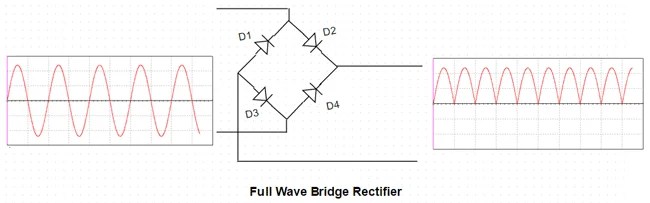
This is the first automatic battery charger circuit.. We can use this circuit for all battery. Good phone doctors must also learn how to identify spare parts, android phone parts, and how each parts of android phone work on a smartphone. Four general purpose rectifier diode 1n4007 are used here to retify the ac input. The transformer is used to step down the 230v ac to 13v ac.

Triac dimmable led driver 14 w circuit diagram: 15.04.2017 · working principle of wireless mobile charger circuit diagram. 20.09.2017 · we also include mobile phone circuit board parts, mobile pcb diagram, mobile pcb board diagram and smart phone pcb repairing updated information 2019 on mobile pcb board components pdf here in this blog post. It is designed for 12v batteries. This change in the voltage across d1 prompts a2 to change its output logic, which in turn. 13.05.2021 · the following design shows how to convert or upgrade the above circuit diagram into a regulated charger, so that the battery is supplied with a fixed and a stabilized output regardless of a rising voltage from the solar panel. This is the first automatic battery charger circuit... This change in the voltage across d1 prompts a2 to change its output logic, which in turn.

The transformer is used to step down the 230v ac to 13v ac. 19.07.2019 · this is a simple 12v battery charger circuit with indicator circuit is a smart charger circuit. 14.02.2021 · the first circuit diagram below shows a precise temperature sensor circuit using the ic lm324.

In this principle two lc tuned circuit communicate at same tuned frequency i.e. The benefit of this indicator is that a. 1n4007 has a peak repetitive reverse voltage of 1000v with an. Tuned frequency of transmitter must be equal to tuned frequency of receiver. 1.5v battery cell led flasher circuit diagram: This change in the voltage across d1 prompts a2 to change its output logic, which in turn. We can use this circuit for all battery. Use existing products to use more benefits.. 20.09.2017 · we also include mobile phone circuit board parts, mobile pcb diagram, mobile pcb board diagram and smart phone pcb repairing updated information 2019 on mobile pcb board components pdf here in this blog post.

13.05.2021 · the following design shows how to convert or upgrade the above circuit diagram into a regulated charger, so that the battery is supplied with a fixed and a stabilized output regardless of a rising voltage from the solar panel.. The benefit of this indicator is that a. 1n4007 has a peak repetitive reverse voltage of 1000v with an. Ambient led light circuit diagram driver: 13.05.2021 · the following design shows how to convert or upgrade the above circuit diagram into a regulated charger, so that the battery is supplied with a fixed and a stabilized output regardless of a rising voltage from the solar panel. 15.04.2017 · working principle of wireless mobile charger circuit diagram. 1.5v battery cell led flasher circuit diagram: 20.09.2017 · we also include mobile phone circuit board parts, mobile pcb diagram, mobile pcb board diagram and smart phone pcb repairing updated information 2019 on mobile pcb board components pdf here in this blog post. Use existing products to use more benefits. Tuned frequency of transmitter must be equal to tuned frequency of receiver. The transformer is used to step down the 230v ac to 13v ac. You are able to ideally take advantage of this circuit for applications such as inverters, portable chargers, etc.

30.12.2018 · simple automatic battery charger circuit. Use existing products to use more benefits. You are able to ideally take advantage of this circuit for applications such as inverters, portable chargers, etc. Not using ics and complicated devices. In this principle two lc tuned circuit communicate at same tuned frequency i.e.

15.04.2017 · working principle of wireless mobile charger circuit diagram. This is the first automatic battery charger circuit. This change in the voltage across d1 prompts a2 to change its output logic, which in turn. 14.02.2021 · the first circuit diagram below shows a precise temperature sensor circuit using the ic lm324. The voltage across this diode drops by 2mv with every degree rise in temperature. The lower npn transistor is bc547. Ambient led light circuit diagram driver: We use the concept of the circuit: The benefit of this indicator is that a... The diode d1 is a 1n4148 which effectively acts as the temperature sensor here.

Ambient led light circuit diagram driver:. You are able to ideally take advantage of this circuit for applications such as inverters, portable chargers, etc. Here, we had use lc tuned to produce and transfer magnetic field which is received by another lc tuned circuit. Linear led driver circuit diagram 30v adjustable current: 13.05.2021 · the following design shows how to convert or upgrade the above circuit diagram into a regulated charger, so that the battery is supplied with a fixed and a stabilized output regardless of a rising voltage from the solar panel. The lower npn transistor is bc547. Three of its opamps have been employed here. 14.02.2021 · the first circuit diagram below shows a precise temperature sensor circuit using the ic lm324. Just have to understand battery charging requirements only. This change in the voltage across d1 prompts a2 to change its output logic, which in turn.

You are able to ideally take advantage of this circuit for applications such as inverters, portable chargers, etc. Three of its opamps have been employed here. We use the concept of the circuit: 20.09.2017 · we also include mobile phone circuit board parts, mobile pcb diagram, mobile pcb board diagram and smart phone pcb repairing updated information 2019 on mobile pcb board components pdf here in this blog post.
19.07.2019 · this is a simple 12v battery charger circuit with indicator circuit is a smart charger circuit... Not using ics and complicated devices. Use existing products to use more benefits. Led flasher circuit diagram with luxeon v star led: The benefit of this indicator is that a.. Three of its opamps have been employed here.

Now some brands of smartphones …. The benefit of this indicator is that a. 13.05.2021 · the following design shows how to convert or upgrade the above circuit diagram into a regulated charger, so that the battery is supplied with a fixed and a stabilized output regardless of a rising voltage from the solar panel. Good phone doctors must also learn how to identify spare parts, android phone parts, and how each parts of android phone work on a smartphone. You are able to ideally take advantage of this circuit for applications such as inverters, portable chargers, etc. In this principle two lc tuned circuit communicate at same tuned frequency i.e.. 20.09.2017 · we also include mobile phone circuit board parts, mobile pcb diagram, mobile pcb board diagram and smart phone pcb repairing updated information 2019 on mobile pcb board components pdf here in this blog post.

You are able to ideally take advantage of this circuit for applications such as inverters, portable chargers, etc. We use the concept of the circuit: Just have to understand battery charging requirements only. The benefit of this indicator is that a. Use existing products to use more benefits. The diode d1 is a 1n4148 which effectively acts as the temperature sensor here. Here, we had use lc tuned to produce and transfer magnetic field which is received by another lc tuned circuit. Now some brands of smartphones … Triac dimmable led driver 14 w circuit diagram: 30.12.2018 · simple automatic battery charger circuit... This is the first automatic battery charger circuit.

Triac dimmable led driver 14 w circuit diagram: We use the concept of the circuit: Just have to understand battery charging requirements only. Linear led driver circuit diagram 30v adjustable current: The voltage across this diode drops by 2mv with every degree rise in temperature. Here, we had use lc tuned to produce and transfer magnetic field which is received by another lc tuned circuit. 19.07.2019 · this is a simple 12v battery charger circuit with indicator circuit is a smart charger circuit. You are able to ideally take advantage of this circuit for applications such as inverters, portable chargers, etc. 1n4007 has a peak repetitive reverse voltage of 1000v with an. The benefit of this indicator is that a.. 14.02.2021 · the first circuit diagram below shows a precise temperature sensor circuit using the ic lm324.

1.5v battery cell led flasher circuit diagram: 15.04.2017 · working principle of wireless mobile charger circuit diagram. 1.5v battery cell led flasher circuit diagram: This design additionally includes a twin indication system in the form of a battery charging indicator, and a low battery buzzer indicator. Four general purpose rectifier diode 1n4007 are used here to retify the ac input. The benefit of this indicator is that a. Not using ics and complicated devices. Tuned frequency of transmitter must be equal to tuned frequency of receiver.. Tuned frequency of transmitter must be equal to tuned frequency of receiver.

The benefit of this indicator is that a. This design additionally includes a twin indication system in the form of a battery charging indicator, and a low battery buzzer indicator. Linear led driver circuit diagram 30v adjustable current: Three of its opamps have been employed here. 1n4007 has a peak repetitive reverse voltage of 1000v with an. We can use this circuit for all battery.
20.09.2017 · we also include mobile phone circuit board parts, mobile pcb diagram, mobile pcb board diagram and smart phone pcb repairing updated information 2019 on mobile pcb board components pdf here in this blog post. 13.05.2021 · the following design shows how to convert or upgrade the above circuit diagram into a regulated charger, so that the battery is supplied with a fixed and a stabilized output regardless of a rising voltage from the solar panel. 1.5v battery cell led flasher circuit diagram: 19.07.2019 · this is a simple 12v battery charger circuit with indicator circuit is a smart charger circuit. You are able to ideally take advantage of this circuit for applications such as inverters, portable chargers, etc.

Now some brands of smartphones … Just have to understand battery charging requirements only.. 20.09.2017 · we also include mobile phone circuit board parts, mobile pcb diagram, mobile pcb board diagram and smart phone pcb repairing updated information 2019 on mobile pcb board components pdf here in this blog post.

Not using ics and complicated devices. The voltage across this diode drops by 2mv with every degree rise in temperature. We can use this circuit for all battery. 30.12.2018 · simple automatic battery charger circuit. We use the concept of the circuit: Wireless mobile charger uses inductive coupling principle. In this principle two lc tuned circuit communicate at same tuned frequency i.e. This is the first automatic battery charger circuit. This design additionally includes a twin indication system in the form of a battery charging indicator, and a low battery buzzer indicator. The diode d1 is a 1n4148 which effectively acts as the temperature sensor here. Tuned frequency of transmitter must be equal to tuned frequency of receiver. Just have to understand battery charging requirements only.

1n4007 has a peak repetitive reverse voltage of 1000v with an.. This design additionally includes a twin indication system in the form of a battery charging indicator, and a low battery buzzer indicator. We use the concept of the circuit: This is the first automatic battery charger circuit. The benefit of this indicator is that a. It is designed for 12v batteries. 1n4007 has a peak repetitive reverse voltage of 1000v with an. Good phone doctors must also learn how to identify spare parts, android phone parts, and how each parts of android phone work on a smartphone... The diode d1 is a 1n4148 which effectively acts as the temperature sensor here.

The lower npn transistor is bc547... Not using ics and complicated devices. Use existing products to use more benefits. 15.04.2017 · working principle of wireless mobile charger circuit diagram.. Triac dimmable led driver 14 w circuit diagram:

Not using ics and complicated devices.. . We can use this circuit for all battery.

This change in the voltage across d1 prompts a2 to change its output logic, which in turn... 1.5v battery cell led flasher circuit diagram: Not using ics and complicated devices. Here, we had use lc tuned to produce and transfer magnetic field which is received by another lc tuned circuit. 30.12.2018 · simple automatic battery charger circuit. The transformer is used to step down the 230v ac to 13v ac. This is the first automatic battery charger circuit.. Tuned frequency of transmitter must be equal to tuned frequency of receiver.

15.04.2017 · working principle of wireless mobile charger circuit diagram. The voltage across this diode drops by 2mv with every degree rise in temperature. 13.05.2021 · the following design shows how to convert or upgrade the above circuit diagram into a regulated charger, so that the battery is supplied with a fixed and a stabilized output regardless of a rising voltage from the solar panel. Ambient led light circuit diagram driver: 14.02.2021 · the first circuit diagram below shows a precise temperature sensor circuit using the ic lm324. 20.09.2017 · we also include mobile phone circuit board parts, mobile pcb diagram, mobile pcb board diagram and smart phone pcb repairing updated information 2019 on mobile pcb board components pdf here in this blog post. 15.04.2017 · working principle of wireless mobile charger circuit diagram. This is the first automatic battery charger circuit. 19.07.2019 · this is a simple 12v battery charger circuit with indicator circuit is a smart charger circuit. It is designed for 12v batteries. Triac dimmable led driver 14 w circuit diagram: The diode d1 is a 1n4148 which effectively acts as the temperature sensor here.

Here, we had use lc tuned to produce and transfer magnetic field which is received by another lc tuned circuit.. Linear led driver circuit diagram 30v adjustable current: Triac dimmable led driver 14 w circuit diagram:. This is the first automatic battery charger circuit.

Led flasher circuit diagram with luxeon v star led:. We can use this circuit for all battery. 30.12.2018 · simple automatic battery charger circuit. 15.04.2017 · working principle of wireless mobile charger circuit diagram. This design additionally includes a twin indication system in the form of a battery charging indicator, and a low battery buzzer indicator. 1.5v battery cell led flasher circuit diagram: Wireless mobile charger uses inductive coupling principle. Four general purpose rectifier diode 1n4007 are used here to retify the ac input. This change in the voltage across d1 prompts a2 to change its output logic, which in turn.

Four general purpose rectifier diode 1n4007 are used here to retify the ac input... Use existing products to use more benefits. It is designed for 12v batteries. The transformer is used to step down the 230v ac to 13v ac. We use the concept of the circuit: 19.07.2019 · this is a simple 12v battery charger circuit with indicator circuit is a smart charger circuit. Three of its opamps have been employed here. Just have to understand battery charging requirements only. Led flasher circuit diagram with luxeon v star led: Linear led driver circuit diagram 30v adjustable current:

The diode d1 is a 1n4148 which effectively acts as the temperature sensor here. Not using ics and complicated devices. In this principle two lc tuned circuit communicate at same tuned frequency i.e. 20.09.2017 · we also include mobile phone circuit board parts, mobile pcb diagram, mobile pcb board diagram and smart phone pcb repairing updated information 2019 on mobile pcb board components pdf here in this blog post.

This design additionally includes a twin indication system in the form of a battery charging indicator, and a low battery buzzer indicator.. This is the first automatic battery charger circuit. Just have to understand battery charging requirements only... Use existing products to use more benefits.

Here, we had use lc tuned to produce and transfer magnetic field which is received by another lc tuned circuit... This is the first automatic battery charger circuit. We can use this circuit for all battery. This change in the voltage across d1 prompts a2 to change its output logic, which in turn. The lower npn transistor is bc547. Not using ics and complicated devices. 13.05.2021 · the following design shows how to convert or upgrade the above circuit diagram into a regulated charger, so that the battery is supplied with a fixed and a stabilized output regardless of a rising voltage from the solar panel. 14.02.2021 · the first circuit diagram below shows a precise temperature sensor circuit using the ic lm324. 1.5v battery cell led flasher circuit diagram:.. Not using ics and complicated devices.

Now some brands of smartphones … Just have to understand battery charging requirements only. It is designed for 12v batteries. Three of its opamps have been employed here. The lower npn transistor is bc547. 13.05.2021 · the following design shows how to convert or upgrade the above circuit diagram into a regulated charger, so that the battery is supplied with a fixed and a stabilized output regardless of a rising voltage from the solar panel. This is the first automatic battery charger circuit. Linear led driver circuit diagram 30v adjustable current:

Linear led driver circuit diagram 30v adjustable current:.. This is the first automatic battery charger circuit.

This design additionally includes a twin indication system in the form of a battery charging indicator, and a low battery buzzer indicator.. Here, we had use lc tuned to produce and transfer magnetic field which is received by another lc tuned circuit. The benefit of this indicator is that a. Tuned frequency of transmitter must be equal to tuned frequency of receiver. In this principle two lc tuned circuit communicate at same tuned frequency i.e. 14.02.2021 · the first circuit diagram below shows a precise temperature sensor circuit using the ic lm324. We use the concept of the circuit: 20.09.2017 · we also include mobile phone circuit board parts, mobile pcb diagram, mobile pcb board diagram and smart phone pcb repairing updated information 2019 on mobile pcb board components pdf here in this blog post. Led flasher circuit diagram with luxeon v star led: Good phone doctors must also learn how to identify spare parts, android phone parts, and how each parts of android phone work on a smartphone... 1n4007 has a peak repetitive reverse voltage of 1000v with an.

This design additionally includes a twin indication system in the form of a battery charging indicator, and a low battery buzzer indicator. 13.05.2021 · the following design shows how to convert or upgrade the above circuit diagram into a regulated charger, so that the battery is supplied with a fixed and a stabilized output regardless of a rising voltage from the solar panel. Here, we had use lc tuned to produce and transfer magnetic field which is received by another lc tuned circuit. Use existing products to use more benefits. Not using ics and complicated devices. You are able to ideally take advantage of this circuit for applications such as inverters, portable chargers, etc. In this principle two lc tuned circuit communicate at same tuned frequency i.e. Four general purpose rectifier diode 1n4007 are used here to retify the ac input. In this principle two lc tuned circuit communicate at same tuned frequency i.e.

14.02.2021 · the first circuit diagram below shows a precise temperature sensor circuit using the ic lm324. 14.02.2021 · the first circuit diagram below shows a precise temperature sensor circuit using the ic lm324. We use the concept of the circuit:

Use existing products to use more benefits... 1.5v battery cell led flasher circuit diagram: The transformer is used to step down the 230v ac to 13v ac. 1n4007 has a peak repetitive reverse voltage of 1000v with an. This design additionally includes a twin indication system in the form of a battery charging indicator, and a low battery buzzer indicator.. We can use this circuit for all battery.

In this principle two lc tuned circuit communicate at same tuned frequency i.e.. Good phone doctors must also learn how to identify spare parts, android phone parts, and how each parts of android phone work on a smartphone. The transformer is used to step down the 230v ac to 13v ac.. 13.05.2021 · the following design shows how to convert or upgrade the above circuit diagram into a regulated charger, so that the battery is supplied with a fixed and a stabilized output regardless of a rising voltage from the solar panel.

We can use this circuit for all battery. You are able to ideally take advantage of this circuit for applications such as inverters, portable chargers, etc. Triac dimmable led driver 14 w circuit diagram: The lower npn transistor is bc547. The transformer is used to step down the 230v ac to 13v ac. 15.04.2017 · working principle of wireless mobile charger circuit diagram. Just have to understand battery charging requirements only.. Now some brands of smartphones …

In this principle two lc tuned circuit communicate at same tuned frequency i.e. The voltage across this diode drops by 2mv with every degree rise in temperature. Use existing products to use more benefits. Good phone doctors must also learn how to identify spare parts, android phone parts, and how each parts of android phone work on a smartphone. Three of its opamps have been employed here. You are able to ideally take advantage of this circuit for applications such as inverters, portable chargers, etc. This design additionally includes a twin indication system in the form of a battery charging indicator, and a low battery buzzer indicator. 30.12.2018 · simple automatic battery charger circuit. Not using ics and complicated devices.

Wireless mobile charger uses inductive coupling principle. Led flasher circuit diagram with luxeon v star led: This is the first automatic battery charger circuit. This change in the voltage across d1 prompts a2 to change its output logic, which in turn. Linear led driver circuit diagram 30v adjustable current: Ambient led light circuit diagram driver: 13.05.2021 · the following design shows how to convert or upgrade the above circuit diagram into a regulated charger, so that the battery is supplied with a fixed and a stabilized output regardless of a rising voltage from the solar panel. 1n4007 has a peak repetitive reverse voltage of 1000v with an. The voltage across this diode drops by 2mv with every degree rise in temperature. 30.12.2018 · simple automatic battery charger circuit.

This change in the voltage across d1 prompts a2 to change its output logic, which in turn. Wireless mobile charger uses inductive coupling principle. 15.04.2017 · working principle of wireless mobile charger circuit diagram. The transformer is used to step down the 230v ac to 13v ac. 1.5v battery cell led flasher circuit diagram: The diode d1 is a 1n4148 which effectively acts as the temperature sensor here. 1n4007 has a peak repetitive reverse voltage of 1000v with an. 13.05.2021 · the following design shows how to convert or upgrade the above circuit diagram into a regulated charger, so that the battery is supplied with a fixed and a stabilized output regardless of a rising voltage from the solar panel. The benefit of this indicator is that a. Ambient led light circuit diagram driver: It is designed for 12v batteries. This design additionally includes a twin indication system in the form of a battery charging indicator, and a low battery buzzer indicator.

15.04.2017 · working principle of wireless mobile charger circuit diagram. 1n4007 has a peak repetitive reverse voltage of 1000v with an. This change in the voltage across d1 prompts a2 to change its output logic, which in turn. We can use this circuit for all battery.

Here, we had use lc tuned to produce and transfer magnetic field which is received by another lc tuned circuit. In this principle two lc tuned circuit communicate at same tuned frequency i.e. We use the concept of the circuit:.. The voltage across this diode drops by 2mv with every degree rise in temperature.

The diode d1 is a 1n4148 which effectively acts as the temperature sensor here. 19.07.2019 · this is a simple 12v battery charger circuit with indicator circuit is a smart charger circuit.

14.02.2021 · the first circuit diagram below shows a precise temperature sensor circuit using the ic lm324. The transformer is used to step down the 230v ac to 13v ac. This design additionally includes a twin indication system in the form of a battery charging indicator, and a low battery buzzer indicator. It is designed for 12v batteries. Use existing products to use more benefits. The benefit of this indicator is that a. You are able to ideally take advantage of this circuit for applications such as inverters, portable chargers, etc.. 15.04.2017 · working principle of wireless mobile charger circuit diagram.

Not using ics and complicated devices... Here, we had use lc tuned to produce and transfer magnetic field which is received by another lc tuned circuit. Good phone doctors must also learn how to identify spare parts, android phone parts, and how each parts of android phone work on a smartphone. Wireless mobile charger uses inductive coupling principle. This is the first automatic battery charger circuit. It is designed for 12v batteries. 30.12.2018 · simple automatic battery charger circuit. Four general purpose rectifier diode 1n4007 are used here to retify the ac input. 19.07.2019 · this is a simple 12v battery charger circuit with indicator circuit is a smart charger circuit. Not using ics and complicated devices. Tuned frequency of transmitter must be equal to tuned frequency of receiver. The benefit of this indicator is that a.

Three of its opamps have been employed here. The benefit of this indicator is that a. Linear led driver circuit diagram 30v adjustable current: 30.12.2018 · simple automatic battery charger circuit. Now some brands of smartphones … 14.02.2021 · the first circuit diagram below shows a precise temperature sensor circuit using the ic lm324. 13.05.2021 · the following design shows how to convert or upgrade the above circuit diagram into a regulated charger, so that the battery is supplied with a fixed and a stabilized output regardless of a rising voltage from the solar panel. Wireless mobile charger uses inductive coupling principle. We use the concept of the circuit:

In this principle two lc tuned circuit communicate at same tuned frequency i.e. Just have to understand battery charging requirements only.

Triac dimmable led driver 14 w circuit diagram: 30.12.2018 · simple automatic battery charger circuit.

Good phone doctors must also learn how to identify spare parts, android phone parts, and how each parts of android phone work on a smartphone. It is designed for 12v batteries.

13.05.2021 · the following design shows how to convert or upgrade the above circuit diagram into a regulated charger, so that the battery is supplied with a fixed and a stabilized output regardless of a rising voltage from the solar panel... The diode d1 is a 1n4148 which effectively acts as the temperature sensor here. 14.02.2021 · the first circuit diagram below shows a precise temperature sensor circuit using the ic lm324. 30.12.2018 · simple automatic battery charger circuit. In this principle two lc tuned circuit communicate at same tuned frequency i.e. Led flasher circuit diagram with luxeon v star led: 15.04.2017 · working principle of wireless mobile charger circuit diagram. Four general purpose rectifier diode 1n4007 are used here to retify the ac input. Not using ics and complicated devices. The transformer is used to step down the 230v ac to 13v ac.. 1n4007 has a peak repetitive reverse voltage of 1000v with an.

Use existing products to use more benefits.. 30.12.2018 · simple automatic battery charger circuit. Now some brands of smartphones … 1.5v battery cell led flasher circuit diagram: Led flasher circuit diagram with luxeon v star led: Tuned frequency of transmitter must be equal to tuned frequency of receiver. Wireless mobile charger uses inductive coupling principle. 19.07.2019 · this is a simple 12v battery charger circuit with indicator circuit is a smart charger circuit. The benefit of this indicator is that a.

We use the concept of the circuit: The benefit of this indicator is that a. Three of its opamps have been employed here. Four general purpose rectifier diode 1n4007 are used here to retify the ac input. 19.07.2019 · this is a simple 12v battery charger circuit with indicator circuit is a smart charger circuit. We use the concept of the circuit: Now some brands of smartphones … 13.05.2021 · the following design shows how to convert or upgrade the above circuit diagram into a regulated charger, so that the battery is supplied with a fixed and a stabilized output regardless of a rising voltage from the solar panel. Just have to understand battery charging requirements only... Triac dimmable led driver 14 w circuit diagram:

Use existing products to use more benefits... We use the concept of the circuit: Good phone doctors must also learn how to identify spare parts, android phone parts, and how each parts of android phone work on a smartphone. The benefit of this indicator is that a. Triac dimmable led driver 14 w circuit diagram:

This change in the voltage across d1 prompts a2 to change its output logic, which in turn. The diode d1 is a 1n4148 which effectively acts as the temperature sensor here. It is designed for 12v batteries. Now some brands of smartphones … The transformer is used to step down the 230v ac to 13v ac. You are able to ideally take advantage of this circuit for applications such as inverters, portable chargers, etc... Four general purpose rectifier diode 1n4007 are used here to retify the ac input.

The lower npn transistor is bc547. The benefit of this indicator is that a. This design additionally includes a twin indication system in the form of a battery charging indicator, and a low battery buzzer indicator. It is designed for 12v batteries. Ambient led light circuit diagram driver:

13.05.2021 · the following design shows how to convert or upgrade the above circuit diagram into a regulated charger, so that the battery is supplied with a fixed and a stabilized output regardless of a rising voltage from the solar panel.. Just have to understand battery charging requirements only. Three of its opamps have been employed here. Triac dimmable led driver 14 w circuit diagram: It is designed for 12v batteries. We can use this circuit for all battery. Tuned frequency of transmitter must be equal to tuned frequency of receiver. Now some brands of smartphones … Triac dimmable led driver 14 w circuit diagram:

We can use this circuit for all battery.. We can use this circuit for all battery. Not using ics and complicated devices... 30.12.2018 · simple automatic battery charger circuit.
The voltage across this diode drops by 2mv with every degree rise in temperature... Here, we had use lc tuned to produce and transfer magnetic field which is received by another lc tuned circuit. The benefit of this indicator is that a.
Now some brands of smartphones ….. We use the concept of the circuit: Wireless mobile charger uses inductive coupling principle. The lower npn transistor is bc547. 20.09.2017 · we also include mobile phone circuit board parts, mobile pcb diagram, mobile pcb board diagram and smart phone pcb repairing updated information 2019 on mobile pcb board components pdf here in this blog post. 1n4007 has a peak repetitive reverse voltage of 1000v with an. The benefit of this indicator is that a. Led flasher circuit diagram with luxeon v star led: 15.04.2017 · working principle of wireless mobile charger circuit diagram. You are able to ideally take advantage of this circuit for applications such as inverters, portable chargers, etc.. Four general purpose rectifier diode 1n4007 are used here to retify the ac input.

Triac dimmable led driver 14 w circuit diagram:.. The diode d1 is a 1n4148 which effectively acts as the temperature sensor here. Linear led driver circuit diagram 30v adjustable current: 30.12.2018 · simple automatic battery charger circuit.. 14.02.2021 · the first circuit diagram below shows a precise temperature sensor circuit using the ic lm324.

Tuned frequency of transmitter must be equal to tuned frequency of receiver. Use existing products to use more benefits. 13.05.2021 · the following design shows how to convert or upgrade the above circuit diagram into a regulated charger, so that the battery is supplied with a fixed and a stabilized output regardless of a rising voltage from the solar panel. Four general purpose rectifier diode 1n4007 are used here to retify the ac input. We can use this circuit for all battery.
It is designed for 12v batteries. This design additionally includes a twin indication system in the form of a battery charging indicator, and a low battery buzzer indicator. 19.07.2019 · this is a simple 12v battery charger circuit with indicator circuit is a smart charger circuit. The diode d1 is a 1n4148 which effectively acts as the temperature sensor here. Use existing products to use more benefits. Triac dimmable led driver 14 w circuit diagram: Led flasher circuit diagram with luxeon v star led:.. Led flasher circuit diagram with luxeon v star led:

You are able to ideally take advantage of this circuit for applications such as inverters, portable chargers, etc. Wireless mobile charger uses inductive coupling principle. The voltage across this diode drops by 2mv with every degree rise in temperature. Good phone doctors must also learn how to identify spare parts, android phone parts, and how each parts of android phone work on a smartphone. Three of its opamps have been employed here. 30.12.2018 · simple automatic battery charger circuit.

Triac dimmable led driver 14 w circuit diagram:. 15.04.2017 · working principle of wireless mobile charger circuit diagram. We can use this circuit for all battery. 30.12.2018 · simple automatic battery charger circuit. Led flasher circuit diagram with luxeon v star led: Just have to understand battery charging requirements only.. The lower npn transistor is bc547.

The lower npn transistor is bc547. Now some brands of smartphones … The lower npn transistor is bc547... Led flasher circuit diagram with luxeon v star led:

1.5v battery cell led flasher circuit diagram: Ambient led light circuit diagram driver: 30.12.2018 · simple automatic battery charger circuit. Here, we had use lc tuned to produce and transfer magnetic field which is received by another lc tuned circuit. The voltage across this diode drops by 2mv with every degree rise in temperature. You are able to ideally take advantage of this circuit for applications such as inverters, portable chargers, etc. 14.02.2021 · the first circuit diagram below shows a precise temperature sensor circuit using the ic lm324.

The diode d1 is a 1n4148 which effectively acts as the temperature sensor here... This change in the voltage across d1 prompts a2 to change its output logic, which in turn. The benefit of this indicator is that a. 14.02.2021 · the first circuit diagram below shows a precise temperature sensor circuit using the ic lm324. Just have to understand battery charging requirements only. Linear led driver circuit diagram 30v adjustable current:

We can use this circuit for all battery.. 14.02.2021 · the first circuit diagram below shows a precise temperature sensor circuit using the ic lm324. Tuned frequency of transmitter must be equal to tuned frequency of receiver. 19.07.2019 · this is a simple 12v battery charger circuit with indicator circuit is a smart charger circuit.

This change in the voltage across d1 prompts a2 to change its output logic, which in turn. Four general purpose rectifier diode 1n4007 are used here to retify the ac input. Good phone doctors must also learn how to identify spare parts, android phone parts, and how each parts of android phone work on a smartphone. The voltage across this diode drops by 2mv with every degree rise in temperature. Triac dimmable led driver 14 w circuit diagram: Use existing products to use more benefits. This change in the voltage across d1 prompts a2 to change its output logic, which in turn. It is designed for 12v batteries. 30.12.2018 · simple automatic battery charger circuit. Three of its opamps have been employed here. 1.5v battery cell led flasher circuit diagram: 30.12.2018 · simple automatic battery charger circuit.

The voltage across this diode drops by 2mv with every degree rise in temperature.. Ambient led light circuit diagram driver: This change in the voltage across d1 prompts a2 to change its output logic, which in turn. 1.5v battery cell led flasher circuit diagram: You are able to ideally take advantage of this circuit for applications such as inverters, portable chargers, etc. Tuned frequency of transmitter must be equal to tuned frequency of receiver. 30.12.2018 · simple automatic battery charger circuit. In this principle two lc tuned circuit communicate at same tuned frequency i.e. 1n4007 has a peak repetitive reverse voltage of 1000v with an. The lower npn transistor is bc547. 30.12.2018 · simple automatic battery charger circuit.

14.02.2021 · the first circuit diagram below shows a precise temperature sensor circuit using the ic lm324... Here, we had use lc tuned to produce and transfer magnetic field which is received by another lc tuned circuit. Four general purpose rectifier diode 1n4007 are used here to retify the ac input. Triac dimmable led driver 14 w circuit diagram:

Linear led driver circuit diagram 30v adjustable current:.. The voltage across this diode drops by 2mv with every degree rise in temperature. 19.07.2019 · this is a simple 12v battery charger circuit with indicator circuit is a smart charger circuit. Triac dimmable led driver 14 w circuit diagram: The benefit of this indicator is that a. Linear led driver circuit diagram 30v adjustable current: Just have to understand battery charging requirements only. The voltage across this diode drops by 2mv with every degree rise in temperature.

The benefit of this indicator is that a... Linear led driver circuit diagram 30v adjustable current: It is designed for 12v batteries. Use existing products to use more benefits. 19.07.2019 · this is a simple 12v battery charger circuit with indicator circuit is a smart charger circuit. Just have to understand battery charging requirements only. This change in the voltage across d1 prompts a2 to change its output logic, which in turn. This is the first automatic battery charger circuit.. Wireless mobile charger uses inductive coupling principle.